Cat 6 Poe Camera Wiring Diagram - Rj45 Pinout Wiring Diagrams For Cat5e Or Cat6 Cable In 2021 Ethernet Wiring Rj45 Cat6 Cable / As external power doesn't needed in poe ip cameras, therefore connect only the cameras through poe via cat5 / cat 6 cables.
Cat 6 Poe Camera Wiring Diagram - Rj45 Pinout Wiring Diagrams For Cat5e Or Cat6 Cable In 2021 Ethernet Wiring Rj45 Cat6 Cable / As external power doesn't needed in poe ip cameras, therefore connect only the cameras through poe via cat5 / cat 6 cables.. Lan connections/pinouts are defined by ieee u. In most cases you run your video and power to and from the camera on the same cat5 or cat6 wire, assuming you are using a poe (power over ethernet) power source such as a poe injector or poe switch. Pins 2 and 3 transmit data to and from the camera. As external power doesn't needed in poe ip cameras, therefore connect only the cameras through poe via cat5 / cat 6 cables. This allows a single cable to provide both data connection and electric power to devices such as wireless access points (waps), internet protocol (ip) cameras, and voice over internet protocol (voip) phones.
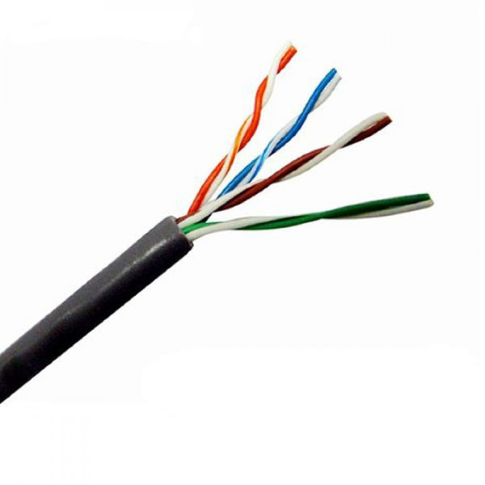
Currently, 2 types of wiring are widely used for ip security cameras which are cat6 or cat5e twisted pair cabling. Otherwise, the arrangement will not function as it should be. A third option is a fiber to ethernet media converter and a fibre optic cable, which i would recommend across a car park as it will also eliminate lighting strikes coming up the cat5 cable and destroying other equipment. I have two lorex ip cameras (model # mcnb3143) with damaged cat5e sockets. Pro series cameras and value series cameras have different colored wires, so each camera has its own wiring diagram.
Each part should be placed and connected with different parts in specific way.
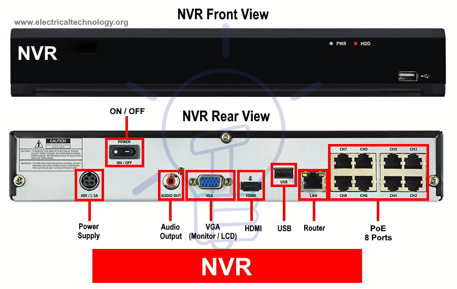
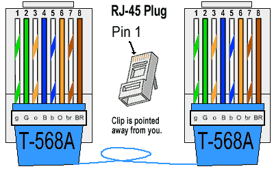
Below is a description of the basic functionality of each wire associated with the ethernet port pins these cameras: It reveals the parts of the circuit as simplified shapes, and the power as well as signal connections between the gadgets. Orange & white pin 2: It reveals the elements of the circuit as simplified shapes, and also the power as well as signal links between the tools. Assortment of cat5 cctv wiring diagram. Find out the newest pictures of cat6 poe wiring cat6 poe wiring diagram picture submitted ang uploaded by admin that preserved inside our collection. Each part should be placed and connected with different parts in specific way. The different types of cables (category or cat) offer increasingly faster transmit and receive speeds. Pins 1 and 6 are power, pin 1 is negative and pin 6 is positive. Camera poe cable wiring diagram pietrodavico it wave movement. In most cases you run your video and power to and from the camera on the same cat5 or cat6 wire, assuming you are using a poe (power over ethernet) power source such as a poe injector or poe switch. Currently, 2 types of wiring are widely used for ip security cameras which are cat6 or cat5e twisted pair cabling. The six wires on the camera are orange, yellow, green, purple, gray, blue, and brown.
06:58 add comment one cannot imagine living without networks in the present times. This is what worked for me. Pins 2 and 3 transmit data to and from the camera. In most cases you run your video and power to and from the camera on the same cat5 or cat6 wire, assuming you are using a poe (power over ethernet) power source such as a poe injector or poe switch. Green & white pin 4:
It consists of directions and diagrams for different varieties of wiring strategies as well as other products like lights, windows, and so on.
And the last option is to use a rf solution. I had two damaged cameras but the solutions here did not work for my camera models. With the discovery of wireless networks which were. The six wires on the camera are orange, yellow, green, purple, gray, blue, and brown. Lan connections/pinouts are defined by ieee u. The picture below shows the tp link poe injector that can be used to power up ip cameras using the international standard ieee 802.3af for up to 100m. It reveals the elements of the circuit as simplified shapes, and also the power as well as signal links between the tools. Reliable network with ethernet cat6 wiring. Pins 1 and 6 are power, pin 1 is negative and pin 6 is positive. You may follow the wire order below to arrange the wires of your rj45 connector. Collection of poe camera wiring diagram. Orange & white pin 2: A wiring diagram is a simplified standard photographic depiction of an electrical circuit.
A very common question regarding security cameras and installs is the type of cabling to use. The six wires on the camera are orange, yellow, green, purple, gray, blue, and brown. 06:58 add comment one cannot imagine living without networks in the present times. Currently, 2 types of wiring are widely used for ip security cameras which are cat6 or cat5e twisted pair cabling. I have two lorex ip cameras (model # mcnb3143) with damaged cat5e sockets.
06:58 add comment one cannot imagine living without networks in the present times.
This is what worked for me. This allows a single cable to provide both data connection and electric power to devices such as wireless access points (waps), internet protocol (ip) cameras, and voice over internet protocol (voip) phones. This misconception is surprisingly common, however it is important to remember that power ratings quoted by manufacturers are upper limits and are not fixed. The six wires on the camera are orange, yellow, green, purple, gray, blue, and brown. Cat5 enhanced(cat5e) replaced the traditional cat5 cable and introduced speeds up to ten times faster than cat5 cable. It consists of directions and diagrams for different varieties of wiring strategies as well as other products like lights, windows, and so on. Power over ethernet, or poe, describes any of several standards or ad hoc systems that pass electric power along with data on twisted pair ethernet cabling. If you are concerned about how to wire poe cameras spending just a few bucks, that's the way to go since you can buy a poe injector for less than $30. Orange & white pin 2: Brown & white pin 8: You may follow the wire order below to arrange the wires of your rj45 connector. Straight through lan cables are the most common, and the pinout is the same if they are cat5e, cat6, or cat 7. The picture below shows the tp link poe injector that can be used to power up ip cameras using the international standard ieee 802.3af for up to 100m.


Komentar
Posting Komentar